Earth resistance testing in Sri Lanka: methods, acceptable values and how often
By Vibhawa Editorial Team · Vibhawa Consultants
An earthing system is buried and forgotten until the day it has to carry a fault or a lightning strike. Testing is the only way to know it will.
Earth resistance testing measures how easily current flows from an earth electrode into the surrounding soil, in ohms (Ω). The standard method is fall-of-potential: a test current is driven between the electrode and a remote spike, and the voltage is measured at a second spike in between. Where the electrode cannot be disconnected, a clamp-on tester measures it in place. For lightning protection, IEC 62305-3 recommends below 10 Ω where possible; for an electrical installation, the test under BS 7671 is whether protective devices will disconnect a fault in time.
Why earth resistance matters
- Fault protection: in a TT installation, where the building has its own electrode and no earth from the supply, the electrode resistance decides whether an RCD can clear an earth fault before metalwork reaches a dangerous voltage.
- Lightning protection: the earth termination has to spread lightning current into the soil without dangerous voltages building up around the building.
- Substations: during an earth fault the whole earth grid rises in voltage, and the safety of anyone standing nearby depends on the step and touch voltages that rise creates.
- Equipment: surge protective devices, generators and sensitive electronics all rely on a sound earth reference.
Test methods
Fall-of-potential (three-pole or four-pole)
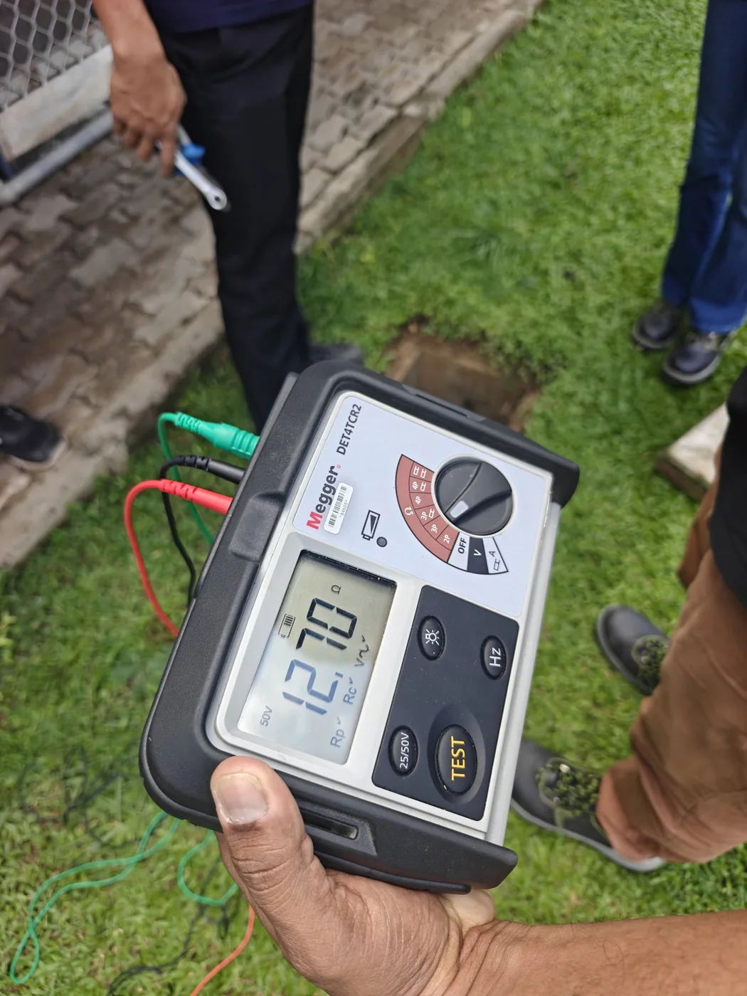
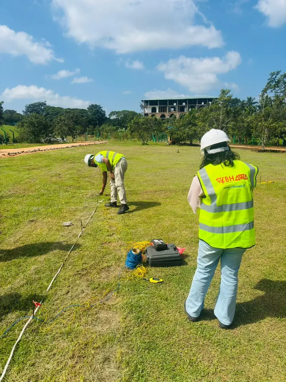
The reference method in IEEE 81 and BS 7430. The electrode under test is disconnected from the installation. A current spike is driven into the ground far enough away that its zone of influence does not overlap the electrode’s; for a single rod this is often 30 m or more, and for a large grid it is several times the grid’s diagonal. A potential spike is placed on the line between them. For a single electrode in uniform soil, the true resistance is read with the potential spike at about 62% of the distance to the current spike. The spike is then moved about 10% either side: if the three readings agree closely, the result is valid. A four-pole connection removes the resistance of the test leads from the reading.
Clamp-on (stakeless)
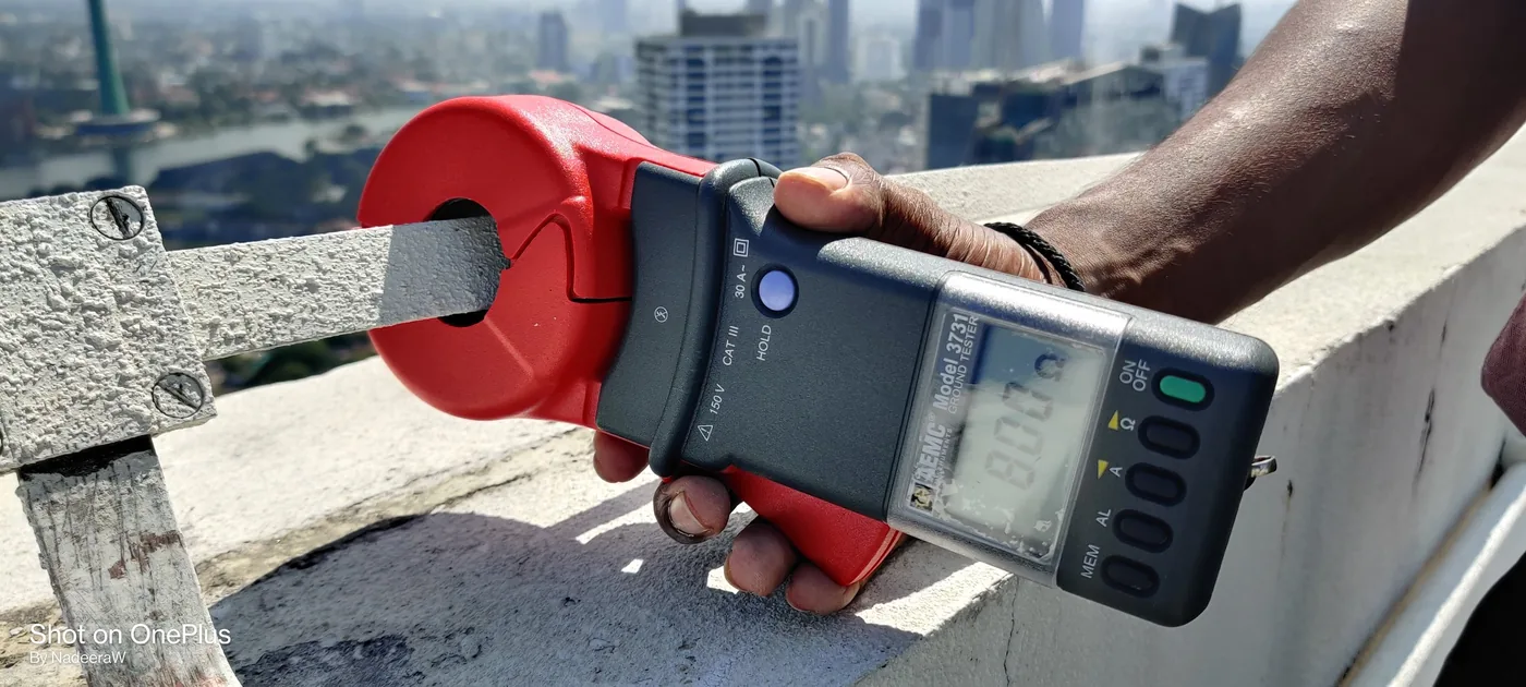
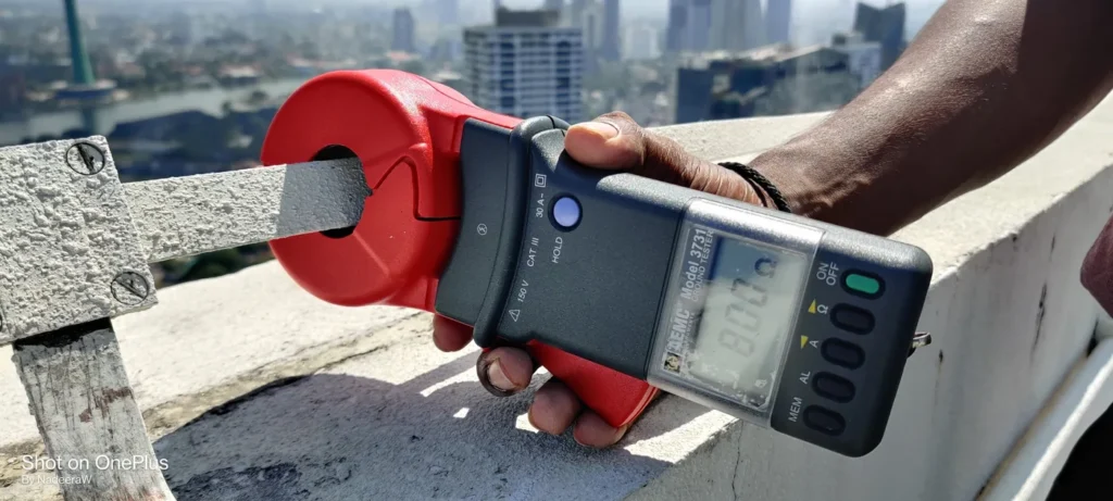
A clamp-on tester induces a voltage in the earth conductor and measures the resulting current, giving the resistance of the loop the electrode forms with the rest of the earthing system. No spikes and no disconnection are needed, which makes it the practical method on rooftops, in paved areas and on live systems. It only works where there are other parallel earth paths, and the reading includes the return path, so it cannot be used on a single isolated electrode and it can read low if the conductor is bonded to a metallic loop above ground.
Selective measurement
A combination of the two: test spikes are used as in fall-of-potential, and a current clamp measures only the current in the electrode under test. It measures one electrode in a connected system without disconnecting it.
Soil resistivity (Wenner four-pin)
Before a new earthing system is designed, the soil itself is measured. Four spikes are placed in a line at equal spacing a; the resistance R between the inner pair gives the apparent resistivity ρ = 2πaR. Repeating the test at several spacings and in two directions shows how resistivity changes with depth, which is what an earthing design needs.
Large substation grids
For a large grid, the distances needed for a reliable fall-of-potential test become impractical. IEEE 81 describes alternatives, such as the slope method and current injection over a long distance, and the grid is assessed on its step and touch voltages as well as its resistance.
What value is acceptable?
There is no single number that applies to every earth. The right figure depends on what the electrode is for.
| Earthing system | Criterion | Reference |
|---|---|---|
| Lightning protection earth termination | Below 10 Ω, measured at low frequency, where possible | IEC 62305-3 |
| Electrical installation, TT system | RA × IΔn ≤ 50 V. With a 30 mA RCD the theoretical limit is about 1,667 Ω, but values above 200 Ω may not be stable, and many designers aim much lower | BS 7671 (411.5.3) and IET Guidance Note 3 |
| Electrical installation, TN system | The earth fault loop impedance (Zs) must be low enough for the circuit breaker or fuse to disconnect in time; the building electrode is supplementary | BS 7671 Chapter 41 |
| Substation earth grid | Step and touch voltages within safe limits. Many project specifications also ask for 1 Ω or less, but the voltage limits are the real test | IEEE 80, EN 50522 and the project specification |
Always compare a reading with the design value and with the previous test. A rising trend tells you more than a single number.
What changes the reading
- Moisture: dry soil has a much higher resistance. A reading taken in the wet season can look far better than the same electrode in a drought, so the dry season gives the worst case.
- Soil type: coastal sand over saline groundwater can give very low values, while rock and laterite inland can be many times higher.
- Corrosion: a corroded clamp or joint adds resistance that has nothing to do with the soil. Joints are measured separately with a micro-ohmmeter.
- Test set-up: spikes too close together, parallel buried metalwork or test leads running side by side all give misleading results.
A safety note
Disconnecting an electrode from a live installation removes the earth from everything it protects. In a TT installation, or on a lightning protection system during a storm, that is dangerous. The electrode should be disconnected only when it is safe to do so, or measured in place by the clamp-on or selective method.
How often to test
Earth electrodes are tested as part of every periodic inspection of an electrical installation, and as part of every complete inspection of a lightning protection system. For industrial premises in Sri Lanka we recommend testing every year. For lightning protection, the common reference is Table E.2 of IEC 62305-3:2010: a complete test every two years for protection levels I and II, every four years for levels III and IV, and every year in critical situations.
What a good test report includes
- Every electrode identified on a drawing or tag, so the next test measures the same point.
- The method used for each reading and the spike distances.
- Soil conditions and the weather at the time of the test.
- Each result against the design value, the standard and the previous test.
- The instrument’s calibration certificate.
- Signature by a qualified engineer, and clear recommendations.
Earthing system testing in Sri Lanka and the Maldives
Vibhawa tests earthing and lightning protection systems for high-rises, hotels, factories, substations and solar plants, with calibrated four-terminal and clamp-on earth testers and reports signed by a Chartered Electrical Engineer. Recent work includes earth resistivity testing for DIMO on the Sampur Grid Substation project, soil resistivity surveys and earthing tests for the Diyajanani floating solar plant, and annual lightning protection and earthing testing at Shangri-La Colombo.
Frequently asked questions
What is a good earth resistance value?
For lightning protection, IEC 62305-3 recommends below 10 Ω where possible. For an electrical installation, the value must let protective devices disconnect a fault in time; for a TT system with a 30 mA RCD, values above 200 Ω may not be stable. Substations are judged on step and touch voltages.
What is the 62% rule?
In a fall-of-potential test on a single electrode in uniform soil, the potential spike placed at 62% of the distance to the current spike gives the true resistance. Moving it 10% either way and getting similar readings confirms the result.
Can earth resistance be tested without disconnecting the electrode?
Yes, with a clamp-on tester or the selective method, provided the electrode is part of a system with other parallel earth paths. A single isolated electrode needs the fall-of-potential method.
What is the difference between earth resistance and soil resistivity?
Earth resistance is a property of a particular electrode in its soil, in ohms. Soil resistivity is a property of the soil itself, in ohm-metres, and is measured before an earthing system is designed.
How often should earthing be tested?
At every periodic inspection of the installation and every complete inspection of the lightning protection system. We recommend once a year for industrial premises in Sri Lanka.
Need your earthing tested?
Send us the earthing layout or the last test report and we will scope the test, say how long it takes on site, and quote.
Sources: IEEE Std 81; BS 7430:2011+A1:2015; IEC 62305-3; BS 7671:2018+A4:2026 and IET Guidance Note 3; IEEE Std 80; EN 50522.