Author name: VibhawAdmynRg1

Thermographer conducting an infrared thermography inspection in a chemical warehouse
Blog, News & Insights

How Thermography Surveys Prevent Electrical Fires in Chemical Warehouses

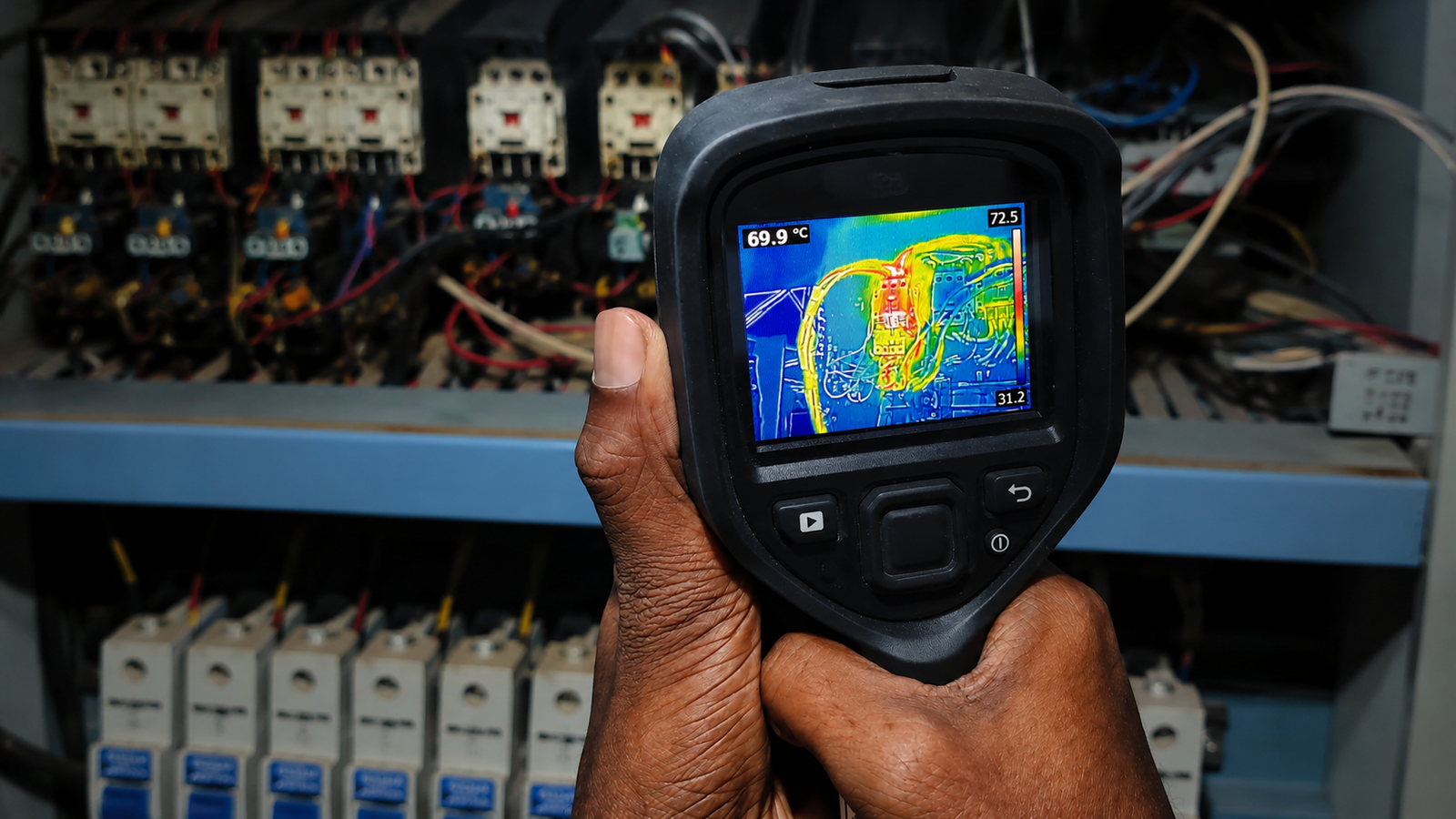
How Thermography Surveys Prevent Electrical Fires in Chemical WarehousesA thermography survey helps identify hidden overheating in electrical systems before visible damage appears. Chemical warehouses carry a higher fire risk because flammable liquids, vapours, packaging materials, and electrical systems often operate within the same facility. In this environment, a small hidden fault can become serious if it is not found early. A loose connection, overloaded breaker, overheating cable, or ageing electrical component may continue working without any visible warning. The panel may look normal, while heat is already building inside. A thermography survey helps detect abnormal heat before visible damage appears. For businesses looking for infrared thermography inspection in Sri Lanka, it is a practical way to identify electrical fire risks, plan repairs, and protect people, stock, and operations before a fault escalates. What is a Thermography Survey? A thermography survey is a non-contact inspection carried out using an infrared thermal imaging camera. The camera detects heat patterns in electrical and mechanical equipment while the system is operating. A trained thermographer then reviews the images to identify abnormal temperature differences. These temperature differences may indicate: Loose electrical connections Overloaded circuits Unbalanced electrical loads Damaged or ageing components Poor ventilation inside panels Developing electrical faults Thermography is most useful when equipment is live and operating under normal or meaningful load. This is important because some electrical faults only appear when current is flowing through the system. A panel may look safe when switched off, but show clear overheating during normal operation. Why Chemical Warehouses Have Higher Electrical Fire Risk Every fire needs heat, fuel, and oxygen. In a chemical warehouse, fuel may already be present through stored chemicals, vapours, cardboard packaging, plastic containers, wooden pallets, drums, and other combustible materials. That makes heat control especially important. Electrical systems can become ignition sources when they are not properly inspected or maintained. Common risks include: Loose or corroded cable connections Overloaded distribution boards Faulty breakers, contactors, or isolators Damaged cable insulation Poor cable terminations Overheating motors or pumps Lighting circuits exposed to dust, heat, or moisture Electrical panels placed close to storage areas In a general commercial building, these issues may lead to breakdowns or repair costs. In a chemical warehouse, they can create wider risks for people, property, inventory, and business continuity. How Thermography Surveys Detect Electrical Fire Risks Thermography does not prevent fire by itself. Its value is in early detection. It gives maintenance and safety teams clear evidence of where heat is building, so they can act before the fault becomes dangerous. Electrical Hot Spots Loose electrical connections are one of the most common causes of overheating. When a connection becomes loose, resistance increases. Higher resistance creates heat. As the connection heats up, it can weaken further and create even more heat. If ignored, this can lead to: Melted insulation Burnt terminals Electrical arcing Panel damage Fire ignition A thermal image can reveal the hot spot before there is visible damage. The maintenance team can then inspect, isolate, and repair the issue before it becomes severe. Overloaded Circuits Chemical warehouses often change over time. New lighting, pumps, ventilation systems, sensors, battery chargers, office areas, or storage zones may be added to the existing electrical network. If the system is not reviewed properly, some circuits may carry more load than they were designed for. A thermography survey can show where breakers, cables, or panels are running hotter than expected. Engineers can then check whether the issue is caused by overload, poor distribution, incorrect equipment selection, or another fault. This helps prevent electrical stress from turning into equipment failure or fire risk. Load Imbalance Many industrial warehouses use three-phase electrical systems. The load should be distributed evenly across the phases. If one phase carries more current than the others, cables, breakers, transformers, and connected equipment can overheat. It can also reduce efficiency and shorten equipment life. Thermography can show uneven heat patterns that may indicate load imbalance. This is useful in warehouses where equipment is frequently added, moved, or modified. Why Visual Electrical Inspections Are Not Enough A panel may look normal in visible light, while thermal imaging shows developing heat-related faults. Visual inspections are still important. They can identify exposed cables, broken covers, corrosion, blocked panel access, poor housekeeping, and unsafe storage near electrical equipment. However, visual checks cannot detect hidden heat. A cable termination may look fine on the outside but still be loose. A breaker may appear normal but run hot internally and a panel may show no visible damage while one section is already overheating. Thermography adds another layer to the inspection process by showing what the naked eye cannot see. Key Areas to Inspect in a Chemical Warehouse A good thermography survey should be planned around the warehouse layout, electrical distribution system, load conditions, and fire risk areas. It should not be limited to a quick scan of the main electrical panel. Key areas to inspect include: Main and sub-distribution boards Motor control centres Transformers Breakers and isolators Cable termination points Contactors and fuse holders Pumps and motors Ventilation and exhaust systems Lighting circuits Battery charging areas Electrical panels near chemical storage zones For chemical warehouses, the inspection plan should also consider site permits, PPE, ventilation, access restrictions, hazardous storage areas, and safe working procedures. The survey should be carried out under realistic load conditions. If it is done during low-load periods, some faults may not show clearly. What a Good Thermography Report Should Include A good thermography report should explain the issue clearly, not only show thermal images. It should include: Thermal images and normal reference images Exact location of each issue Description of the fault Risk level or severity Likely cause Recommended corrective action Repair priority For chemical warehouses, the report should be clear enough for engineers, safety officers, warehouse managers, and decision-makers to understand the risk and next step. Thermography as Part of Electrical Fire Prevention Thermography is valuable, but remember, it should not be your only safety measure. Companies that invest in regular

Vibhawa engineers performing protection relay testing on a solar PV grid-connection panel using a FREJA 300 test set
Blog, News & Insights

What Is Protection Relay Testing and Why Is It Critical for Electrical Safety?

What Is Protection Relay Testing and Why Is It Critical for Electrical Safety?   When a fault occurs on an electrical network, every millisecond matters. A protection relay that fails to operate correctly can lead to transformer and cable damage, switchgear failure, extended outages, lost production, and serious safety incidents. Protection relay testing is what confirms — before a real fault does — that the protection relay will detect that fault and trip the right breaker at the right time. For any facility that depends on reliable power — a factory, a hotel, a hospital, a solar plant or a substation — testing verifies that the protection system will respond correctly at the one moment it truly matters. Key takeaways Protection relay testing confirms a protection relay will detect a fault and trip correctly — instead of finding out it won’t during an actual fault. Testing alone is not enough. A protection relay can pass every test and still be set wrong for the network it protects. A protection coordination study defines the correct settings; testing verifies them. For solar and grid-connected plants, relay testing is also a grid-connection requirement (for example, CEB acceptance in Sri Lanka). Test reports should be reviewed and signed by a chartered electrical engineer — the deliverable that satisfies compliance, insurance and utility sign-off. What Is a Protection Relay? A protection relay is a device that monitors electrical parameters and identifies abnormal operating conditions. When a fault is detected, the protection relay sends a trip command to a circuit breaker or other protective device to isolate the affected section of the network. The objective is straightforward: to protect people, equipment, and electrical infrastructure from damage. Protection relays are commonly installed in: Industrial facilities and manufacturing plants Electrical substations Commercial buildings Power plants and renewable energy projects Data centres Water and wastewater treatment facilities Without protection relays — and without confidence that they are set and working correctly — a fault can spread through a network and destroy expensive equipment in moments. Why Protection Relay Testing Is Important for Electrical Safety Protection systems are installed on the expectation that they will perform correctly. But settings drift, components age, firmware changes, and installation errors can sit undetected for years. Testing confirms that a protection relay still operates according to the original protection philosophy. Professional protection relay testing services verify settings, trip functions, communication schemes, and overall protection performance under simulated fault conditions. This delivers four practical benefits. Prevent Equipment Damage Faults place severe stress on transformers, motors, cables, generators and switchgear. A protection relay that trips too late can let a contained fault escalate into a major failure. Routine testing — combined, for transformers, with regular transformer testing — gives a clearer picture of equipment condition and risk. Improve Personnel Safety Electrical faults can create dangerous conditions, including arc flash. Fast, accurate fault clearing reduces exposure to these hazards. Pairing relay testing with an electrical safety audit assesses hazards, compliance gaps and protection performance together. Reduce Unplanned Downtime Unexpected electrical failures interrupt production, delay operations and drive up maintenance cost. Testing surfaces weaknesses in the protection system before they cause an outage. Support Compliance and Insurance Requirements Many facilities keep documented test records as part of compliance and risk-management programmes. Test reports provide evidence that protection systems are maintained to recognised engineering practice — and are often required by insurers and utilities. What Happens When a Protection Relay Fails? Protection relay failures are rarely obvious. A protection relay can look perfectly operational while a critical setting has been changed or an internal issue has developed. When this happens, the consequences can include: Transformer and motor damage Switchgear faults Arc flash incidents Extended power interruptions Production shutdowns In the worst case, a fault that should have been isolated within milliseconds spreads across a much larger section of the network. This is exactly why relay testing should be treated as a preventive measure — not a reaction to failure. Types of Protection Relays and Their Testing Requirements Different protection functions call for different test procedures. The table below summarises the most common protection relay types and what testing confirms for each. Protection relay type ANSI code What testing verifies Overcurrent 50 / 51 Pickup current, time-current curve, instantaneous trip, grading with upstream/downstream devices Earth fault 50N / 51N Sensitivity, pickup threshold, trip timing Differential 87 Operating pickup, bias/restraint slope, in-zone fault tripping, through-fault stability Voltage / frequency 27/59, 81 Correct operation when voltage or frequency moves outside set limits Grid-interface (solar/DG) U/O V, U/O F, ROCOF, vector shift Anti-islanding and grid-protection response required for utility grid connection Distance 21 Zone reach and fault-response accuracy (mainly transmission/utility networks) Overcurrent (50/51) and differential (87) protection are the workhorses across industrial, commercial, hospitality and renewable sites, so they receive the most attention in practice. Distance protection (21) is included for completeness but is mainly a transmission- and utility-network function. For solar PV and generator-connected sites, the grid-interface functions deserve particular care: under/over voltage, under/over frequency, ROCOF and vector-shift protection govern how the plant connects to — and disconnects from — the grid during a disturbance. These are not optional extras; they are the functions the utility checks before approving grid connection. Vibhawa handles this end to end for renewable-energy plants: the protection system study, relay configuration, and testing, through to the witness verification performed in front of utility engineers to secure the grid connection. We have delivered this for numerous MW-scale solar PV plants connecting to the grid. Grid-connection protection — MW-scale solar track record Vibhawa has carried out protection system studies, relay configuration, testing and utility witness verification for grid-connected solar PV plants including the 3 MW Cheval Blanc open-sea floating plant (Maldives), the 1.6 MW Pyramid Lanka solar project, a 1.16 MW solar PV plant for Jay Jay Mills, and rooftop solar grid-connection support for Warwick Solar Power — alongside protection-coordination work for grid-connected power plants such as the 10 MW Ace Power waste-to-energy facility, Sri Lanka’s first. What

Arc flash safety awareness session conducted by Vibhawa Consultants for Fonterra Sri Lanka maintenance team
Blog, News & Insights

Vibhawa Completes Arc Flash Study and Electrical Safety Audit at Fonterra Sri Lanka

Vibhawa Completes Electrical Audit and Arc Flash Study for Fonterra Sri Lanka Manufacturing Plant An arc flash study is one of the most consequential pieces of work a manufacturing plant can commission, because the findings affect personnel safety, protective device settings, and how the maintenance team is allowed to work near energised equipment. Electrical issues in a plant rarely show up as a single visible fault — they begin as heat, poor selectivity, ageing connections, incorrect protection settings, or work practices that no longer match the way the plant operates. That is why a proper electrical safety audit must go beyond a visual checklist. We, at Vibhawa Consultants, recently completed the annual electrical audit and thermography survey of the Fonterra Sri Lanka manufacturing plant for the fifth consecutive time. This year’s work also included a protection coordination study and arc flash study for the complete electricity distribution system, covering the 33kV system and low voltage network. The project concluded with an arc flash safety awareness session for Fonterra’s maintenance team, followed by a Q&A discussion. Here’s everything you need to know about this: Project Scope This assignment brought together three connected areas of engineering work: Annual electrical audit of the manufacturing plant Infrared thermography survey of live electrical assets Protection coordination and arc flash analysis across the full distribution system For a facility that depends on continuous production, each part serves a different purpose. The audit checks the wider condition, safety and compliance position of the installation. The infrared thermography inspection helps identify abnormal heating while equipment is in service. The protection coordination and arc flash study reviews how the network behaves during fault conditions and what exposure may exist for personnel working near energised equipment. Together, these activities give the maintenance and engineering teams a clearer basis for decisions. Why Electrical Safety Audits Matter in Manufacturing Facilities Manufacturing plants like Fonterra carry a different level of electrical dependency from many commercial sites. Production equipment, utilities, refrigeration, packaging, process control and maintenance access all depend on stable power. A fault in one section can affect more than one machine. So, if protection settings are not selective, a local issue can lead to a wider interruption. A structured electrical safety audit helps plant teams understand: Where immediate electrical hazards may exist Whether maintenance priorities are correctly ranked Which defects require shutdown planning How safety and production continuity are connected Whether past corrective actions have held over time For Fonterra, the fifth consecutive annual assessment also added continuity. Repeated checks help compare the current condition against previous observations. This is important because risk changes as load, asset condition and operating demands change. What an Infrared Thermography Survey Reveals in a Live Plant The thermography survey was a key part of the project as it allowed us to inspect live equipment without interrupting plant operation. Thermal imaging is useful for identifying early warning signs such as: Loose cable terminations Overheated joints Phase imbalance Excessive loading Poor contact resistance Deteriorating components inside panels These findings are valuable only when they are interpreted correctly. A thermal anomaly on non-critical equipment does not carry the same operational consequence as a similar reading on a main distribution panel. Vibhawa’s assessment considered the asset, load condition and location of each finding. This helped Fonterra’s maintenance team prioritise action based on practical risk rather than temperature readings alone. This is where condition monitoring becomes more than inspection. It becomes a planning tool to reduce unplanned failures. How a Protection Coordination Study Improves Plant Reliability The protection coordination study reviewed how protective devices should operate during a fault. The objective is simple: the device closest to the fault should isolate the affected section where possible, while upstream supply remains available. When this does not happen, one fault can shut down a larger part of the plant. That’s why we studied the full distribution arrangement, including the 33kV system and the low voltage network, since coordination cannot be judged by one voltage level alone. A protection study typically considers: Fault levels Protective device settings Time-current behaviour Selectivity between upstream and downstream devices Equipment ratings System response during abnormal conditions Better coordination can reduce the scale of interruption, support safer fault isolation and help maintenance teams understand how the network is expected to respond. This also connects naturally with protection system testing, where protection relays, circuit breakers, CTs, VTs and related circuits are checked against intended performance. What an Arc Flash Study Tells You About Worker Exposure The arc flash study added another safety layer to the project. Arc flash analysis evaluates the potential incident energy released during an arcing fault and helps determine the level of hazard faced by personnel working near energised equipment. This is not only a compliance exercise. It affects daily work decisions.The study helped us identify where higher exposure may exist across the distribution system. It also supports decisions around: Safe working boundaries Personal protective equipment Equipment labelling Switching practices Isolation procedures Work authorisation and supervision This is critical because Fonterra’s system includes both 33kV and low voltage assets. Work at these levels requires a clear understanding of the hazard, not general assumptions. Awareness Session on Arc Flash Safety After the studies were completed, our engineering experts at Vibhawa lead by Sandika Sawandi – Power System Design & Simulation Engineer of Vibhawa conducted an arc flash safety awareness session for Fonterra’s maintenance team. This step matters because technical reports are only useful when the people responsible for operation understand how to apply the findings. The session covered why protection coordination matters, and how maintenance decisions should account for exposure. The Q&A allowed the team to raise questions about plant access, equipment and work routines. This made the project more useful at site level. It connected engineering analysis with the decisions maintenance staff make during inspections, switching and fault response. How Vibhawa Combines Field Testing, System Studies, and Safety Training This project reflects Vibhawa’s strength in field testing, system studies and practical guidance. The work connected: Electrical

Sri Lanka’s first female level two infrared thermographer - Vibhawa | Electrical Testing & Consultancy
News & Insights, Blog

Sri Lanka’s first female level two infrared thermographer

From Intern to Industry Pioneer: A Proud Milestone for Vibhawa and Women in Engineering We are delighted to share that Malki Madapatha, Assistant Manager – Testing & QA, has officially been certified as a Level 2 Infrared Thermographer. This makes her Sri Lanka’s first female Level 2 thermographer — a personal milestone for Malki, and a significant one for the industry as a whole. A Milestone for Sri Lankan Engineering Malki’s journey reflects what we stand for at Vibhawa. She started her career with us as an intern and grew through dedication, curiosity, and hands-on field experience into a specialist in one of the most technical and niche disciplines in electrical engineering. Today she stands among a rare group of professionals globally with advanced thermography credentials, and as one of the first women in Sri Lanka to reach this level, she represents a powerful step forward for women in engineering and STEM. What Level 2 Thermographer Certification Means Level 2 is not an entry-level qualification. Malki’s certification is issued by IRISS, a globally recognised training authority whose Level 2 (CAT 2) programme is designed to meet and exceed ISO 18436 Part 7 and ANSI/ASNT CP-105 and CP-189 recommended practices — the international standards that govern condition monitoring and non-destructive testing personnel. Reaching Level 2 is demanding by design. Candidates must already hold a current Level 1 certification and demonstrate at least 420 hours of documented field experience in infrared thermography before they are eligible to take the course. The Level 2 programme itself covers advanced infrared theory, equipment calibration, error source identification, quantitative report generation, and the assignment of repair priorities based on thermal severity. Certification is granted only after successful completion of the course, a written exam, and a field assignment. In practice, a Level 2 thermographer in Sri Lanka — or anywhere — is qualified to lead inspections independently, interpret quantitative thermal data rather than just spot patterns, provide technical direction to Level 1 personnel, and generate the kind of engineering reports that insurance companies, plant owners, and certifying authorities can act on. Why This Matters for Industrial and Commercial Facilities Infrared thermography is a non-contact, non-destructive technique for identifying hidden electrical faults — loose connections, overloaded conductors, failing breakers, deteriorating insulation — before they cause downtime, fires, or equipment loss. For data centres, hospitals, hotels, manufacturing plants, and critical infrastructure, a routine thermal inspection programme is one of the highest-return preventive maintenance investments available. The quality of a thermography survey, however, depends almost entirely on the thermographer behind the camera. A Level 1 operator can flag anomalies. A Level 2 thermographer can quantify them, prioritise them, and produce reports that engineering teams and insurers will rely on. That is the difference Malki’s certification makes for our clients. Vibhawa’s Thermography Capability With this certification, Vibhawa continues to be the only company in Sri Lanka with both Level 3 and Level 2 certified thermographers in-house. Our thermography team operates under ISO 9001:2015 quality management (SGS/UKAS certified) and delivers infrared thermography services across Sri Lanka and the Maldives, supporting our broader electrical testing and commissioning capability. Where Our Thermographers Have Worked Malki and our wider thermography team have delivered surveys not only across Sri Lankan industrial and commercial sites but also on international projects, including resort properties in the Maldives such as Cheval Blanc Randheli. This combination of local depth and overseas project exposure is what allows us to serve clients with high-stakes assets and tight reliability requirements. Inspiring the Next Generation More than anything, we hope Malki’s achievement encourages more young women in Sri Lanka to step into engineering and pursue specialised technical careers with confidence. At Vibhawa we don’t just practice thermography — we are committed to sharing knowledge, building expertise, and shaping the future of the industry through upcoming training and learning initiatives. If you would like to discuss a thermography survey for your facility, or learn more about our testing capability, please get in touch with our team. Media Coverage The Sunday Times — Malki breaks new ground as first female infrared thermographer Ada Derana Biz English — Vibhawa strengthens industry leadership

Vibhawa is Now an ISO 9001 Certified Electrical Consultancy in Sri Lanka - Vibhawa | Electrical Testing & Consultancy
Blog, News & Insights

Vibhawa is Now an ISO 9001 Certified Electrical Consultancy in Sri Lanka

Vibhawa Consultants is now an ISO 9001 certified electrical consultancy in Sri Lanka. Officially certified to ISO 9001:2015 by SGS, we now meet the global standard for quality management across our electrical testing, inspection, thermography, and power system simulation services. At Vibhawa Consultants, quality has always been part of how we work. From high voltage testing to power  system studies, our focus has been on delivering accurate results that clients can trust. This certification reflects how our processes, reporting systems, and internal controls are now aligned with internationally recognised quality standards. Here’s everything you need to know about this: What is ISO 9001:2015 in Electrical Testing? ISO 9001:2015 is the global standard for quality management systems (QMS). It sets out how a company should manage its processes to ensure consistent, reliable, and traceable outcomes. In electrical consultancy and testing, this is especially important because the work involves: High voltage systems/low voltage systems and critical infrastructure Technical measurements that must be precise Engineering decisions that impact safety and operations Without structured quality systems, there is always a risk of variation in results, reporting gaps, or missed details. ISO 9001 addresses this by ensuring: Standardised processes across all projects Proper documentation at every stage Accountability and traceability for every outcome Continuous improvement across the total value chain In many international projects, especially in power, infrastructure, and industrial sectors, ISO-certified inspectors are usually preferred for this very set of reasons. By achieving this certification, we, at Vibhawa, also align with these global practices while continuing to operate with a strong understanding of local systems and conditions. What Has Changed at Vibhawa Consultants ISO 9001 is not just a label. It reflects how the work is carried out every day. Here are the key improvements that directly impact our clients. 1. Standardised Electrical Test Reports with Better Clarity All our reports now follow a consistent structure aligned with ISO 9001 requirements. This improves clarity in how results are presented, consistency across different projects, and traceability of data and findings. Reports are now easier to review, compare, and use for decision-making. 2. Cloud-Based, Paperless Reporting System We have moved to a fully digital, paperless reporting system which was co-developed with YUGA. Reports are now generated, reviewed, and delivered through a cloud-based platform. This reduces delays, eliminates physical documentation errors, and ensures that clients always have access to their reports at any time. 3. Defined Workflows for Every Service Whether for high voltage testing, thermographic surveys, or power system studies, each service now follows a documented and repeatable workflow. This means every project, regardless of size or location, follows the same standard operating procedures. 4. Real-Time Quality Checks During Testing ISO 9001 requires in-process verification. For us, this means quality checks are now embedded into the testing process itself, not just at the end. Issues can be identified earlier, reducing the risk of inaccurate results or incomplete data. 5. Faster, More Organised Project Delivery With standardised processes and digital tools, project timelines are more predictable. Clients experience more consistent turnaround times and clearer communication at every stage of a project. The Benefits for Clients of an ISO 9001 Certified Electrical Consultancy in Sri Lanka Choosing an ISO 9001 certified electrical consultancy in Sri Lanka means more than a quality badge. It means working with a company that has systems in place to protect your investment and your project outcomes. Greater Confidence in Results When every step of the process follows a defined standard, the results are more reliable. Whether it is a test report, a power system study, or a thermographic inspection, you can trust that the output is based on a validated and consistent process. Consistency Across All Projects Whether it is a power plant, factory, or commercial building, the same level of quality is maintained regardless of the scope or complexity of the project. Improved Transparency Every step of the work is documented and traceable, giving you full visibility into how your project was handled and how conclusions were reached. Faster Turnaround Times With our digital reporting system, delivery is more efficient without compromising quality. You receive your reports faster, with no loss in accuracy or detail. Raising the Standard for Electrical Testing in Sri Lanka and Beyond Electrical testing services in the region are evolving. Clients today expect more than just technical execution. They expect clear documentation, reliable data, and accountability in reporting. By becoming an ISO 9001 certified electrical consultancy in Sri Lanka, we are contributing to raising this standard. We are combining global quality systems with practical engineering expertise suited to local environments. Why This Matters When Choosing an Electrical Consultant in Sri Lanka When selecting an electrical consultancy in Sri Lanka, certifications like ISO 9001 should not be seen as a formality. They indicate how seriously a company takes the accuracy of its work, the structure of its processes, and its responsibility towards clients. For critical systems, this makes a real difference. It reduces risk, improves decision-making, and ensures long-term reliability. Work With Vibhawa — ISO 9001 Certified Electrical Consultancy in Sri Lanka ISO 9001:2015 certification marks an important milestone for Vibhawa Consultants as a leading ISO 9001 certified electrical consultancy in Sri Lanka. It strengthens how we deliver our services and reinforces our commitment to quality, consistency, and transparency. For our clients across power generation, industrial facilities, commercial buildings, and infrastructure projects, this means better service, better documentation, and better outcomes. If you have a project that requires certified, high-quality electrical testing, inspection, or consultancy services in Sri Lanka, contact us today.

3D thermal substation inspection - DJI drone thermal imaging interface showing 33kV gantry and transformer yard heat mapping
Blog

3D Thermal Substation Inspection: Drone Thermography for MV Infrastructure

3D Thermal Substation Inspection: Drone Thermography for MV Infrastructure 3D thermal substation inspection using drone thermography represents a significant advance in condition monitoring for energised medium voltage assets. Substations are designed for reliability. Yet most failures begin quietly with a loose connector, a degrading insulator or a bushing under thermal stress. These defects rarely show up until a trip, fire risk, or forced outage occurs.Infrared thermography has long been used to detect abnormal heat patterns in energised systems. It is a proven method. But traditional handheld scans capture isolated images. They show what is hot at a single moment, without revealing how heat interacts across surrounding structures or how patterns evolve over time.From a reliability standpoint, that limitation matters.Thermal drone inspection for substations and medium voltage infrastructure expands thermography from isolated snapshots to measurable system-level insight. It improves visibility across 11kV, 33kV, and higher voltage installations where access, safety, and spatial continuity are critical. The Limits of Conventional Substation Thermography Traditional substation thermography involves a technician scanning panels, gantries, and transformer connections using a handheld infrared camera.This method has three practical constraints. 1. Line-of-sight limitations Elevated busbars, rear terminations, and outdoor gantries are difficult to access safely. Inspections may require climbing or working close to energised conductors, increasing risk and limiting coverage. 2. Lack of spatial continuity A 2D thermal image isolates a component. It does not show how heat distributes across an entire bay, how phases compare under load, or whether neighbouring structures are affected. 3. Inconsistent measurement baselines Manual inspection angles and distance variations reduce repeatability. Long-term comparison becomes less reliable when geometry is not controlled.Standards such as NFPA 70B and IEC maintenance guidelines recommend routine inspection of electrical systems under load. However, compliance alone does not guarantee meaningful insight. The inspection method also determines the quality of data collected. Why Use 3D Thermal Substation Inspection? Drone thermography inspection uses UAV platforms equipped with calibrated radiometric thermal cameras. These systems capture high-resolution temperature data while maintaining a safe distance from energised equipment.When thermal imaging is integrated with 3D spatial mapping, overlapping images are combined into a measurable digital model of the substation. Each thermal anomaly is located within a defined coordinate system.This delivers four engineering advantages. 1. Full Spatial Context Instead of reviewing isolated images, engineers can evaluate heat patterns across entire structures. Phase imbalance, connector degradation, and insulator heating can be analysed in relation to surrounding components.For 33kV outdoor yards and complex gantry layouts, this broader context supports clearer root cause assessment. 2. Precise Geolocation Each anomaly is tagged to a specific structural location. Maintenance teams can identify the exact clamp, cross arm, or bushing without interpretation errors.This reduces inspection-to-repair time and improves planning accuracy. 3. Repeatable Historical Comparison Because the geometry is mapped, future inspections can be aligned with previous datasets. Temperature rise trends can be tracked at the same physical point over time.This enables trend analysis rather than one-time detection. Substation thermography shifts from identifying faults to monitoring degradation behaviour. 4. Safer Inspection of Energised Infrastructure UAV-based thermal inspection reduces the need for climbing structures or approaching live equipment. For high-risk environments such as transformer yards and live bus structures, this is a direct safety improvement aligned with IEC and IEEE safety practices. Technical Foundations Behind 3D Thermal Modelling Modern drone thermal systems typically include: Radiometric cameras with high thermal sensitivity   GPS-stabilised flight control   Visual spectrum cameras for alignment   Software for photogrammetry and 3D reconstruction During inspection, overlapping thermal images are captured from multiple angles. The software reconstructs a point cloud model where each coordinate contains temperature data.Unlike conventional imaging, engineers can extract temperature values at any location within the model after the inspection is complete. Heat distribution patterns can be analysed across structural components, not just individual connections.Because inspections are conducted under operational load, resistive heating caused by loose connections or degradation becomes detectable. Wider spatial coverage improves the likelihood of identifying imbalance across phases or adjacent assemblies.This structured dataset becomes part of a broader electrical condition monitoring program rather than a standalone report. Standards and Compliance Thermal drone inspection supports established maintenance frameworks. NFPA 70B recommends routine infrared inspection to detect deterioration in electrical systems.   IEC maintenance guidance emphasises condition-based monitoring for critical infrastructure.   ISO 18436 defines qualification requirements for personnel conducting thermography. Plus, when inspections are performed by certified Level 2 and Level 3 thermographers, data interpretation meets recognised professional standards.For utilities, industrial plants, and renewable EPC projects, structured documentation strengthens audit readiness and insurance alignment. Strategic Value in Reliability Programs Maintenance programs usually focus on visible defects or recent failures, while the hidden degradation receives attention only when it escalates.By mapping thermal behaviour across entire substations, drone thermography improves visibility into early-stage heating and structural patterns.This supports: Data-driven maintenance prioritisation   Reduced unplanned outage risk   Improved lifecycle planning   More accurate repair scoping For medium voltage infrastructure, a single forced outage can exceed the cost of structured condition monitoring. Reliability performance depends on early detection and consistent measurement.Thermal drone inspection becomes one layer within a broader engineering framework that includes electrical testing, protection coordination, and structured asset monitoring. Where Vibhawa Fits Implementing thermal drone inspection for substations and medium voltage infrastructure requires more than equipment. It requires engineering interpretation, system knowledge, and compliance awareness.At Vibhawa Consultants, drone thermography is integrated within our wider electrical condition monitoring and medium voltage assessment services. Inspections are conducted by certified thermographers with electrical engineering expertise in MV systems up to 33kV and above.Our approach focuses on measurable asset behaviour, not just image capture. We analyse thermal data within the context of system design, load conditions, and operational risk. This supports structured reliability planning rather than isolated fault detection. Are You Seeing the Full Picture in Your Substation Inspections? Most facilities still rely on periodic 2D thermal scans. The issue is not whether they detect heat, but whether they provide actionable insight across the full spatial and lifecycle context of the asset.Expanding thermography into a mapped, repeatable system improves

Electrical Design, Consultancy for Lanka Walltiles Vibhawa
News & Insights, Blog, work

Vibhawa’s Electrical Design & Consultancy for Lanka Walltiles Expansion

Vibhawa’s Electrical Design Expertise in the Lanka Walltiles PLC Expansion Project When a leading manufacturing company like Lanka Walltiles PLC expands, every system behind that growth must be equally ready to perform, efficiently, safely, and sustainably. To support their continued growth in Sri Lanka’s industrial arena, we, at Vibhawa Consultants, were entrusted to handle the electrical design and engineering consultancy for the expansion of their manufacturing facility in Meepe. This project not only reflects our technical expertise but also our deep commitment to building reliable, future-ready energy systems that empower industries to scale with confidence. Here’s how it was done: Understanding the Client and Their Vision Lanka Walltiles PLC has long been a pioneer in Sri Lanka’s tile and ceramic industry. The company is known for its innovation, quality, and sustainable manufacturing practices. With demand on the rise, the company planned to expand its Meepe manufacturing facility, aiming to increase production capacity while maintaining energy efficiency, system safety, and long-term reliability. That’s where we Vibhawa came in, as their engineering design consultant and trusted technical partner. Our team was responsible for translating their expansion goals into a robust and efficient electrical distribution system that could support the increased operational load while aligning with international standards, as we always do. Vibhawa’s Role as the Client’s Engineer As the client’s engineer, we acted as an independent technical representative for Lanka Walltiles PLC throughout the entire project. Backed by our expertise in electrical consultancy, we made sure every technical and design decision aligned with the client’s operational and safety objectives. Our responsibilities included: Understand client requirements and carry out the electrical design accordingly (33kV and downstream low voltage systems) Reviewing and validating all possible design options Ensuring compliance with IEC standards and safety codes. Assisting for Technical Matters Coordinating between the client, contractors, and suppliers. Supervising key milestones to guarantee design integrity and performance Verifying the bills raised by the selected contractors for the purpose of payments This role required a balance between technical precision and practical decision-making, ensuring the project progressed smoothly while meeting both performance and cost targets. Designing a Future-Ready Electricity Distribution System One of the core scopes of this project was the electrical design and detailed planning of the facility’s distribution system. The expansion added new transformers to increase the site’s overall installation capacity. This was a critical step to handle the additional production load. Our team designed a system that was not only scalable and efficient but also on par with the client’s sustainability goals. Key design elements included: Optimized power distribution networks for improved load management. Integration of redundancy and protection systems to improve reliability. Selection of equipment based on lifecycle cost, performance, and safety. Along with our practical engineering insight and advanced modeling tools, we ensured that the system design delivered long-term operational efficiency while minimizing maintenance and downtime risks. ETAP Modelling and Simulation for Precision At Vibhawa, we believe great design is possible only with solid data. Using ETAP (Electrical Transient Analyzer Program), our engineers built a comprehensive simulation model of the facility’s electrical network. This helped us evaluate multiple operational scenarios and optimize the system before implementing. Through load flow analysis, short-circuit calculations, and protective coordination studies, we identified the most efficient configurations to ensure system stability and safety. ETAP modelling helped us: Predict system performance under different load conditions. Optimize transformer use and cable sizing. Validate protection settings for fault tolerance and continuity. The result? A design that was not only compliant but intelligently optimized, balancing performance, safety, and cost. Value Engineering: Building Smart, Cost-Effective Solutions Engineering is not just about building strong systems. It’s also about building smart. This is why we refined each design decision through value engineering to deliver the best possible outcome within the client’s budget. This process included: Evaluating material choices and system configurations for cost efficiency. Improving energy efficiency through optimized layouts and equipment selection. Reducing long-term operational costs through maintainable and modular design. Being one of the leading electrical engineering services in Sri Lanka, every recommendation we made was supported by technical justification and lifecycle cost analysis. This ensured Lanka Walltiles PLC gained measurable value, both technically and financially. Technical Evaluation and Contractor Support Beyond design, our role further extended into technical evaluations during the procurement and contractor selection phase. We assisted the client in reviewing the bids received for the tenders, conducting comparative analyses, and verifying compliance with design and performance requirements. Our team also provided expert input during negotiations, ensuring that selected contractors had the right technical capabilities to execute the work efficiently and safely. This collaboration gave Lanka Walltiles PLC the confidence that every implementation partner was technically competent, compliant, and matched with project goals. Supervision and Verification to Ensure It’s Done Right Designing a great system is one thing, while making sure it’s implemented to the same standard is another. Vibhawa’s engineering supervision team remained closely involved throughout the project’s construction phase, verifying that all installations, testing, and commissioning were carried out as per design and safety standards. We also handled final bill verification, ensuring financial transparency and that all completed work matched the contractual and technical expectations of the client. This hands-on approach helped maintain quality control and guaranteed that the system’s actual performance met the precision we designed on paper. Delivering Results that Power the Future By the completion of this project, Lanka Walltiles PLC’s Meepe facility was equipped with an electrical system that was: Technically optimized and future-ready. Scalable for expanding production capacity. Compliant with IEC standards and safety codes. Designed for operational reliability and efficiency. But more than just an engineering win, this project represented a true partnership, where collaboration, technical insight, and trust came together to support an industry leader’s growth journey. Powering Industrial Growth, the Vibhawa Way! We, at Vibhawa Consultants, see every industrial and manufacturing project as a chance to make an impact. We want to help businesses grow sustainably, operate efficiently, and achieve long-term energy reliability. Simply put, we combine technical know-how with

Engineers at Vibhawa Consultants performing IEC-compliant field energy meter calibration
Blog, News & Insights

Energy Meter Calibration Services by Vibhawa Consultants

Ensuring Energy Meter Accuracy: Why Field Calibration Matters More Than Ever While everyone has turned energy-conscious today, accuracy isn’t just a technical term. It has now become a business essential. Whether you manage a factory, commercial building, or a power distribution network, your energy meter is the foundation of every decision about cost, efficiency, and performance. Even a small inaccuracy can quietly drain money, distort energy reports, and affect sustainability goals. That’s why regular energy meter calibration is so important; it keeps your measurements reliable, your energy management strategies effective, and your operations fully compliant with global standards like IEC and ISO 50001. At Vibhawa Consultants, we now offer field energy meter calibration services in Sri Lanka, helping businesses verify their energy meters on-site, accurately and efficiently, without downtime. Want to know how? Keep reading. Why Does Energy Meter Accuracy Matter? Your energy meter is like the heartbeat of your facility. It tracks how much power/energy flows in and out. But even a 2% error in readings can cost thousands of rupees each month. Accurate meters ensure: Fair billing: You only pay for the power you actually use. Energy efficiency tracking: Reliable data helps measure savings from your efficiency initiatives. Compliance: Many standards and regulators require verified meters. Sustainability reporting: Accurate data supports carbon footprint assessments and ESG goals. ISO 50001 certification: The standard specifically requires calibrated and verified measurement equipment. Simply put, when your energy meter is off, everything from power quality analysis to cost reporting becomes unreliable. What Is Field Energy Meter Calibration? Field calibration is the process of checking and verifying an energy meter’s accuracy on-site, without removing it from service. At Vibhawa, we use IEC-compliant Class 0.05 field calibrators, the same standard used internationally for high-precision verification. This ensures the process is both safe and highly accurate. Our engineers perform a series of non-intrusive tests, including voltage, current, power factor, and frequency checks, while your facility continues to operate normally. Learn more about our testing and commissioning services to see how we ensure system reliability across all energy infrastructure projects. Following International Standards (IEC Framework) We follow key International Electrotechnical Commission (IEC) standards as follows to ensure your meters meet global accuracy benchmarks: IEC 62052-11: Defines general requirements and environmental conditions for energy meter testing. IEC 62053 Series: Specifies accuracy classes for meters (Class 0.2S, 0.5S, 1, and 2). IEC 60736: Covers reference standards and testing equipment, ensuring calibration tools are significantly more accurate than the meters being tested. By following these frameworks, we, at Vibhawa, ensure traceable, certified, and internationally compliant calibration results, the same level of assurance demanded by energy regulators and industrial clients worldwide. Here’s a Step-by-Step Guide on How Field Calibration Works As mentioned above, our calibration process is designed for accuracy, transparency, and minimal disruption. And most importantly without any down time! 1. Pre-Calibration Preparation: We review meter specifications, prepare customized test protocols (to suit different energy meters/brands/models), and coordinate with your facility team for safe access. 2. Ambient Condition Verification: Field conditions like temperature and humidity are verified using integrated sensors to ensure compliance with IEC standards. 3. Non-Intrusive Connection: We test meters while they remain fully operational using precision voltage tapping and clamp-on current transformers. 4. Testing at Multiple Loads: We simulate various load points (from 5% to 100%) and power factors to confirm the meter’s accuracy across real-world operating conditions. 5. Error Analysis & Reporting: The results are then compared with the calibrator’s reference data. Any deviation is calculated, analyzed, and documented. 6. Certification & Recommendations: A full report is issued, including environmental conditions, error percentages, and compliance verification. The Real Benefits of Field Calibration Regular field calibration provides both technical and financial advantages: Zero Downtime: Meters stay in service during testing. Accurate Results: Tests are conducted in real operating conditions. Cost Efficiency: No need for meter removal or transport. Early Fault Detection: Identifies wiring or transformer issues early. Compliance Support: Helps maintain ISO 50001 and regulatory standards. Together, these benefits help companies optimize their energy management systems (EnMS) and build a stronger foundation for sustainability. ISO 50001 and Calibration Requirements Remember, if your organization is pursuing ISO 50001 Energy Management System certification, calibration is not optional; it’s a must. The standard requires that all measurement equipment be calibrated and verified periodically, with proper records maintained. We help clients achieve this with condition monitoring services and maintain compliance by providing: Detailed calibration documentation and traceability reports. Assistance in defining calibration intervals and acceptance criteria. Integration with ongoing energy monitoring systems for continuous improvement. Technology Behind Our Calibration at Vibhawa At Vibhawa, we use Class 0.05 high-precision reference standards, among the most accurate in the industry. Our high end equipment delivers: Voltage accuracy: ±0.05% Current accuracy: ±0.05% Power accuracy: ±0.05% Frequency accuracy: ±0.05% This ensures our reference standards are four times more accurate than the meters being tested, as required by IEC 60736. So, Who Needs Energy Meter Calibration? Field energy meter calibration is ideal for: Industrial and commercial buildings with high-load equipment. Power plants and substations. Manufacturing facilities pursuing ISO 50001 certification. Businesses with energy monitoring or load management systems. Utilities and facility management companies for ensuring billing accuracy. Future of Energy Meter Verification As technology evolves, calibration practices are becoming smarter and more connected: IoT and Smart Meters: Remote data validation and real-time diagnostics. AI-Driven Predictive Maintenance: Identifying drift and performance changes early. Blockchain Records: Secure, transparent calibration traceability. Vibhawa stays ahead of these advancements, continuously upgrading our methods and equipment to deliver next-generation energy solutions. Vibhawa’s Edge in IEC-Compliant Calibration With our experience in electrical testing, renewable energy systems, and condition monitoring, Vibhawa brings a complete understanding of how energy data drives better business decisions. Our IEC-compliant energy meter calibration services combine technical precision with practical application, helping you maintain accuracy without interrupting operations. Ready to Get Your Energy Meters Calibrated? Accurate data means confident decisions. Whether you’re optimizing energy use, ensuring compliance, or aiming for ISO 50001 certification, Vibhawa Consultants can help. We provide

Power System Modelling for Snowy Hydro 2.0 | ETAP Simulation by Vibhawa
Blog, News & Insights

Power System Modelling for Snowy Hydro 2.0 | ETAP Simulation by Vibhawa

How Vibhawa Consultants Power the Snowy 2.0 Project with Cutting Edge Advanced Power System Modelling & Simulation   Today, we are going to discuss about Electrical Consultancy for Snowy 2.0 by Vibhawa Consultants. Today, the global energy sector is undergoing a massive transformation, with renewable energy projects taking the lead in providing sustainable, reliable, and efficient power. Among these initiatives, Australia’s Snowy 2.0 Project stands out as one of the largest and most ambitious pumped hydroelectric projects in the world. As a company specializing in electrical consultancy, we, at Vibhawa Consultants, played a critical role in modelling and optimising the electrical infrastructure of this landmark project. In this blog, we’ll take a closer look at Vibhawa’s contribution to the Snowy 2.0 Project through advanced ETAP modelling and why our expertise in electrical engineering is trusted worldwide. The Snowy 2.0 Project The Snowy 2.0 Project is an extension of the original Snowy Mountains Hydro-electric Scheme and represents a transformative step in Australia’s energy future. The project involves connecting the existing Tantangara and Talbingo dams through an underground network of tunnels and a power station. Snowy 2.0 is designed with a total generation capacity of 2,200 megawatts to store and release energy on demand, providing critical grid stability and supporting renewable energy integration. The project also holds 350,000 MegaWatt hours of energy storage. This is enough to power around 3 million households for an entire week! The infrastructure includes over 100 substations, extensive underground tunnels, and advanced electrical systems. Ensuring that this network is safe, efficient, and reliable needs advanced engineering expertise. That’s where Vibhawa Consultants stepped in.   Vibhawa’s Role in Snowy 2.0 The Snowy 2.0 electrical modelling contract was presented to us by Future Generation Joint Venture, the main contractor handling the project’s civil and electro-mechanical works. Our ETAP modelling team was responsible for simulating and analysing the electrical network of over 100 substations, covering multiple voltage levels (voltage classification as per Australian standards), including: High Voltage: 33 kV, 22 kV Medium Voltage: 11 kV, 1,000 V Low Voltage: 415 V Here, the objective was to ensure the network could handle high loads, operate safely, and remain resilient in various operational scenarios. Key Areas of Focus Load Flow Analysis Our team conducted comprehensive load flow simulations to determine the optimal distribution of electricity across the substations. This ensured that power could be delivered efficiently during peak and off-peak periods including seasonal variations. Short Circuit Analysis Short circuit study is a critical study which can impact the upstream grid as well as the project infrastructure during a fault. Vibhawa’s engineers modelled fault scenarios to identify potential risks (including worse case scenarios) and recommended solutions for mitigation. This included identifying the optimal making and breaking capacities of circuit breakers both in low voltage and high voltage level.  Protection Coordination Study Proper coordination of protective devices, such as circuit breakers and protection relays, is critical to prevent cascading failures. We ensured that all protection systems were coordinated accurately to improve safety and reliability. Arc Flash Studies Arc flashes pose serious risks to people and equipment. Our ETAP modelling included arc flash analysis to assess hazard levels and implement safety measures. By combining these elements, our Vibhawa team ensured that Snowy 2.0’s electrical network is robust, efficient, and safe, supporting one of the world’s largest renewable energy storage systems. Why is ETAP Modelling Critical for Mega Energy Projects? ETAP (Electrical Transient Analyzer Program) is a leading software tool for power system modelling, simulation, and analysis. For a complex project like Snowy 2.0, ETAP provides: Accurate simulation of electrical networks under normal and fault conditions. Predictive analysis to optimize load flow, short circuits, and protection schemes. Safety evaluation through arc flash and protective device coordination studies. We were able to simulate real-world operating scenarios via ETAP to identify potential issues before they arise, and recommend engineering solutions to improve performance. This proactive approach saves time, reduces costs, and ensures long-term system reliability. Challenges and Solutions in Snowy 2.0 Modelling Working on Snowy 2.0 was both challenging and rewarding. Below are some of the key challenges we faced: 1. Managing Multiple Voltage Levels The project involved a diverse range of voltage levels (33kV down to 415V), which required meticulous modelling and analysis to ensure proper integration and coordination. 2. Large-Scale Network Simulation The project included over 100 substations. So, simulating the entire network in ETAP required detailed planning and advanced technical expertise. 3. Ensuring Safety and Compliance Arc flash and short circuit risks had to be carefully modelled to comply with international standards in electrical safety. Vibhawa Consultants addressed these challenges through a highly skilled ETAP team, systematic testing, and a rigorous validation process. Through this, we were able to deliver reliable results for the Future Generation Joint Venture and Snowy Hydro. The Impact of Vibhawa’s Work on Snowy 2.0 By modelling the Snowy 2.0 electrical infrastructure, Vibhawa Consultants has helped ensure: Reliable power distribution across high, medium, and low voltage networks. Improved safety for personnel and equipment through arc flash and short circuit analysis. Efficient grid performance, supporting renewable energy integration and peak demand management. Long-term sustainability of one of Australia’s most significant energy projects. This work highlights the value of professional electrical consultancy in large-scale renewable energy projects and positions Vibhawa Consultants as a trusted partner for complex electrical system testing and commissioning. Ready to Level Up Your Projects with Expert Electrical Consultancy? Vibhawa Consultants is proud to provide world-class electrical engineering services not just in Sri Lanka, but across the globe. From renewable energy projects in Australia to industrial infrastructure in the Maldives, Qatar, and Austria, our projects showcase international experience, advanced ETAP modelling, and proven engineering expertise to deliver safe, efficient, and reliable electrical solutions for large-scale projects. Whether it’s renewable energy, industrial infrastructure, or complex electrical networks, our team ensures your systems operate optimally from day one. Contact us today to discuss your project and discover how we can elevate your electrical infrastructure. #ElectricalConsultancy #ETAPModelling #RenewableEnergyProjects #ElectricalEngineering #Snowy2.0Project #PowerSystemSafety #IndustrialElectricalSolutions

Vibhawa project team inspecting and testing the solar inverter setup
work, Blog, News & Insights

Standard Chartered Rooftop Solar Project by Vibhawa Consultants | A Landmark in Sri Lanka’s Clean Energy Journey

Standard Chartered Bank’s Sri Lanka head office is now generating clean, reliable energy thanks to a rooftop solar PV project designed and supervised by Vibhawa Consultants. From feasibility studies and detailed design to testing, commissioning, and performance analysis, we guided the bank every step of the way. This has helped them reduce energy costs, cut carbon emissions, and lead the way in corporate sustainability. Discover how we turned this renewable energy vision into reality. The Challenge Standard Chartered Bank had one clear goal: bring renewable energy into its head office operations, reduce its dependence on grid electricity, and contribute to its global sustainability agenda. But installing a solar PV system on a corporate rooftop is no simple task. It requires careful feasibility studies, accurate design, precise simulations, and thorough supervision. Every stage must be handled with technical accuracy to ensure the system performs reliably for decades. This is where Vibhawa stepped in, combining our engineering expertise with sustainability know-how. The Journey with Vibhawa 1. Starting with a Feasibility Study and Design Every strong project begins with a solid plan. Our team conducted a detailed feasibility study of the bank’s head office rooftop to assess the building’s suitability for solar panel installation. This included examining roof structure, load-bearing capacity, orientation, and shading. Once the feasibility was confirmed, the concept was turned into a detailed design for the solar PV system. This ensured that the installation would be technically sound, safe, and aligned with Standard Chartered’s energy goals. 2. Predicting the System Performance/Energy Yield with PVsyst Simulation Before even placing a single solar panel, we used PVsyst simulation software to model how the system would perform under real conditions. This advanced simulation allowed us to: Estimate the accurate energy yield. Predict system performance over the years. Identify the best configuration for maximum efficiency. Give the bank clarity on savings, return on investment, and contribution to sustainability targets. In simple words, PVsyst helped answer the question: “How much energy can we expect from this rooftop solar project?”. This ensured that there’s no guesswork in the design. 3. Preparing the Project Plans and Tender With feasibility and simulation complete, it was time to prepare the technical tender package, including a Bill of Quantities (BOQ). This step was crucial.  A strong tender makes sure everything is transparent, competitive, and up to international standards. By doing so, Standard Chartered could confidently select contractors and equipment suppliers, knowing the system would be built on the right technical foundation. 4. Acting as the Client’s Engineer and Supervisor Being the client’s engineer meant more than just overseeing paperwork. Our team represented Standard Chartered throughout the project lifecycle, ensuring the bank’s interests were safeguarded at every step. This included: Supervising the installation of the solar panels and related electrical systems. Checking compliance with international engineering and safety standards. Coordinating with contractors to make sure the project stayed on track and met quality requirements. In short, Vibhawa stood as a trusted partner to this project, making sure the rooftop solar system was not just built but built right. 5. Testing, Commissioning, and Performance Analysis Once installation was complete, the final stage was testing and commissioning the solar PV system. Vibhawa’s engineers carried out rigorous checks to confirm the system was functioning exactly as designed. The electrical tests included (but not limited to) – earth fault loop impedance and resistance to earth testing (to ensure correct earthing integrity), insulation resistance testing of the cable (to ensure cables are in good condition after installation). To ensure the solar side performance verification, we used a calibrated Solar PV Analyzer (Seaward PV210) to conduct performance analysis. This process verified that every solar panel and component delivered the guaranteed performance from day one. By matching real test results with the earlier PVsyst simulation, Vibhawa proved that the solar project would achieve the energy savings and green goals Standard Chartered aimed for. The Outcome Today, the rooftop solar PV system at Standard Chartered Bank’s head office is more than just an energy project. We see it as a symbol of leadership in sustainability. Below are the benefits they get to enjoy now: Less dependency on grid electricity and a step towards Standard Chartered Bank’s path towards Net Zer The bank now generates a significant portion of its own energy. Lower electricity bills: Clean energy reduces operating costs in the long run. Lower carbon footprint: Every kilowatt of solar power contributes to Sri Lanka’s fight against climate change. Corporate leadership: The project sets an example for other organizations in the region, proving that corporations can lead the transition to renewable energy. Why Does This Project Matter? This rooftop project is not just about solar panels and power. It is about vision, leadership, and responsibility. By investing in rooftop solar, Standard Chartered has shown that corporations can take meaningful steps toward building a sustainable future for Sri Lanka as a whole as per their sustainability agenda. For Vibhawa, it was an opportunity to showcase how our expertise in engineering consultancy, supervision, and testing can transform a renewable energy project from an idea into a long-lasting success. From feasibility studies and detailed solar PV design to system testing and commissioning, the entire project reflects the value of having an experienced partner like us to guide the journey. Our Broader Mission At Vibhawa, every project is seen as part of a bigger picture. Our mission is to help businesses, industries, and institutions embrace renewable energy confidently. By offering expertise in solar PV design, performance analysis, supervision consultancy, and condition monitoring, we ensure that clients don’t just adopt renewable energy, but do so in a way that is reliable, efficient, and future-ready. Ready to Take the Next Step Towards Clean Energy? The Standard Chartered Bank rooftop solar project is more than just a milestone for the bank. It’s a step forward in Sri Lanka’s renewable energy journey specially in the financial sector. It shows that with the right expertise, clean energy can be both impactful and profitable. At Vibhawa, we take

At Vibhawa, we offer state-of-the-art Electrical Consultancy, Testing, Condition Monitoring and Engineering Services designed for the needs of tomorrow’s world.

Services

Electrical Testing

Infrared Thermography

Electrical Consultancy

Electrical Design

Compliance Monitoring

Other Services

Recent news

  • All Post
  • Blog
  • News & Insights
  • work

© 2025 Vibhawa Consultants. Site By Remnis Global

Scroll to Top