June 25, 2026

An arc flash is a sudden, explosive release of energy through the air — heat beyond the surface temperature of the sun, a pressure blast, molten metal — over in a fraction of a second. Whether the person at that panel walks away comes down to two numbers: how much energy reaches them, and how fast the upstream device clears. An arc flash study calculates both at every working position, and turns the result into a label your team can act on.
Every arc flash study produces two headline results for each point in the system. Together they define the protection a worker needs and how close anyone may approach live equipment.
The thermal energy a worker could absorb at a defined working distance during an arc flash. It sets the minimum arc rating of the PPE required for the task — and whether the task should be done live at all.
The distance within which incident energy could cause a second-degree burn — 1.2 cal/cm². Beyond it, no arc-rated PPE is required for the arc hazard. Inside it, nobody stands without it.
Under IEEE 1584-2018 the calculated incident energy depends on several interacting factors. Change any one and the hazard changes with it — which is why a study that guesses at any of them is a study that guesses at the answer.
The longer a fault burns, the more energy it releases. Available fault current is largely fixed by the network. Clearing time is not — it is set by the protection characteristics and the arcing current at that location. Which means protection settings directly determine arc flash severity.
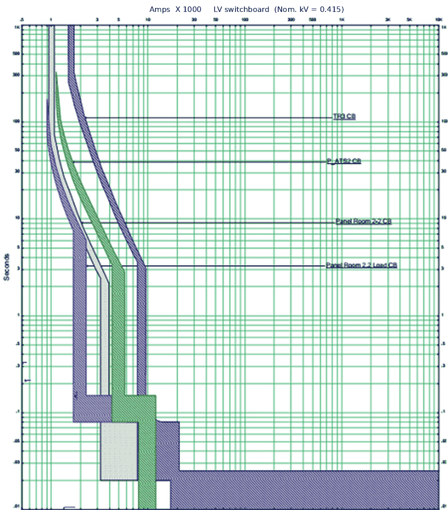
We regularly find positions where the energy is dangerous not because the fault current is high, but because an upstream relay was set generously to avoid nuisance tripping. The curves on the right are from one of our own studies: each band is a protective device, and the separation between them is what decides whether a fault is cleared locally or takes out the incomer — and how long the arc burns.
This is why an arc flash study and a protection coordination study are scoped together.
Every busbar can have a different fault current, arcing current, enclosure and upstream protective device — so the result is evaluated separately at each one. For each, the study identifies the governing fault and its clearing device, then reports the incident energy, the arc flash boundary, the shock approach boundaries and the data behind them.
The protective device and its clearing time are inputs to that calculation, not a separate list of results. That is why the findings are organised location by location — the way the people who will use them think about the plant.
NFPA 70E turns the study into practical measures. Under the incident-energy method, the arc rating of the PPE for a task must be at least the calculated incident energy at the working distance. The categories below are the common equivalence; the governing rule is the number, not the category.
| Category | Incident energy | Minimum arc rating | Typical arc-rated clothing |
|---|---|---|---|
| Below threshold | < 1.2 cal/cm² | — | No arc-rated PPE required for the arc hazard. Long-sleeve natural-fibre clothing, safety glasses, hearing protection and leather footwear as site rules require. |
| Category 1 | 1.2 – 4 cal/cm² | 4 cal/cm² | Arc-rated shirt and trousers or coverall, arc-rated face shield or hood, hard hat, safety glasses, hearing protection, leather gloves. |
| Category 2 | 4 – 8 cal/cm² | 8 cal/cm² | Arc-rated shirt and trousers or coverall, arc-rated hood or face shield with balaclava, hard hat, safety glasses, hearing protection, leather gloves. |
| Category 3 | 8 – 25 cal/cm² | 25 cal/cm² | Arc-rated flash suit jacket and trousers over arc-rated clothing, flash suit hood, insulating gloves with leather protectors. |
| Category 4 | 25 – 40 cal/cm² | 40 cal/cm² | Arc-rated flash suit rated 40 cal/cm² or more, flash suit hood, insulating gloves with leather protectors. |
| Above 40 | Dangerous | — | No energised work. De-energise, lock out and tag out before approaching. The study recommends what has to change for that position to become workable. |
PPE is the last layer, not the first. It sits inside a risk assessment that prioritises safer measures — de-energising where feasible, reducing clearing times, and safe work practice — before anyone is dressed for the hazard.
This is the label format we supply, with illustrative values. It carries everything the person standing at that panel needs: the arc flash boundary, incident energy at the working distance, the PPE category and the minimum arc rating that goes with it, the shock hazard and both approach boundaries, the glove class — and, the part most labels omit, the specific upstream device that clears a fault at this bus.
Supplied print-ready, formatted to IEEE 1584-2018 and NFPA 70E, for your team to print and affix. One for every position a person can work at while energised: switchboard incomers, feeder and load breakers, motor starters and MCC buckets, and the load terminals of motors, capacitor banks and large static loads. Each names its equipment and its source device, so there is no guesswork about which panel it belongs on — and no position quietly left out of the count.
Every result traces back to a modelled network in ETAP — load flow, short circuit, protection coordination and arc flash on one coordinated model. The label is the last page of a study, not a product on its own.
A maintained licence is why the calculation is to the 2018 revision of IEEE 1584 and not the one before it. Licence certificate available on request.
Incident energy changes with how the plant is running. We model each configuration that puts people in front of live equipment — normal utility supply, generator or island mode, bus-tie closed, maintenance switching engaged — and the label carries the worst case. A study that models one scenario has priced itself low for a reason.
We have written up one of our arc flash studies for Fonterra's Sri Lankan operation — why it was commissioned and what came out of it. Read the Fonterra case →
The licence is the cheap part. The model build, the data chase, the judgement on which scenario governs, and the Chartered Engineer's signature an insurer accepts are the work. ETAP computes; the engineering is the judgement either side of it, and the accountability underneath.
Drawings, nameplate and cable data, device settings and utility fault levels — built into a validated ETAP model. Gaps come back to you as a specific checklist of what to read off the equipment. No site visit.
Arcing currents established at every bus, and the clearing time of the device that governs each location — proven on the model, not assumed.
Incident energy and arc flash boundary computed per busbar to IEEE 1584-2018, for every operating scenario that applies.
Print-ready labels for every energised working position — incomers, feeders, motor starters, load terminals — matched to the equipment they describe.
PPE category mapping and approach boundaries aligned with NFPA 70E, and what to do about the positions nobody should work on live.
Mitigation options — settings, maintenance switching, equipment measures — ordered from free to expensive, signed by a Chartered Electrical Engineer.
A study that produces only numbers has done half the job. The recommendations report sets out, for your system, which of these will move a position into a lower category and what each one costs.
Faster, well-coordinated clearing cuts incident energy without losing selectivity. Usually the cheapest fix available.
A temporary reduced-energy setting that lowers the hazard only while staff are working on the equipment.
Lets a downstream device signal upstream so a close-in fault is tripped instantly rather than after a grading delay.
Light-and-current sensing that clears an arcing fault in milliseconds rather than cycles.
Directs arc energy and gases away from personnel by design. Effective, and the most expensive option here.
The safest state is no energy. Where work can be done dead, that always comes first.
Almost nobody commissions an arc flash study unprompted. The trigger is usually one of four things, and which one it is changes what the study has to satisfy:
Tell us which applies and we scope to what that party will accept, rather than producing a study that has to be redone.
Any facility where staff or contractors work on or near energised equipment. It is the basis for selecting correct PPE, setting approach boundaries and complying with NFPA 70E. There is no blanket legal requirement in Sri Lanka or the Maldives — the obligation usually arrives through a parent company, an insurer or an audit.
At least every five years, and whenever the system changes materially — new equipment, revised protection settings, or a change in the utility fault level. Any of those can change incident energy. A study predating the 2018 revision of IEEE 1584 is worth re-checking regardless.
Single-line diagrams, equipment nameplate data, cable sizes and lengths, protective device types and settings, the utility fault level, and the working distances and enclosure types for the positions to be labelled. Incomplete records are the norm — we tell you precisely what to read off the equipment, and the study is built from your data without a site visit.
Incident energy and boundaries to IEEE 1584-2018. PPE selection and safe work practice to NFPA 70E. For Australian clients, the Energy Networks Association's NENS 09-2014 guideline where the network operator requires it.
A short circuit study gives fault current. An arc flash study uses that, plus how fast protection clears, to work out the energy a person would absorb. You cannot do the second without the first, which is why it is inside the scope.
Often, yes. Because clearing time is a major driver, relay optimisation, maintenance switching or zone-selective interlocking can bring a location into a lower category. The recommendations report sets out the options for your system, ordered by cost.
We supply them print-ready, one per energised working position, and your team prints and affixes them. Fitting is the one step that has to happen on the floor, and it is quicker for the people already there.
Two to four weeks from complete data for a large industrial facility, depending on size and complexity. The clock starts when the data is complete, not when the order is placed — which is why we tell you early exactly what is missing.
Send the single-line diagram and tell us who requires the study — insurer, parent company or auditor. That tells us what it has to satisfy, and we scope and quote from there.
Electrical Testing
Infrared Thermography
Electrical Consultancy
Electrical Design
Compliance Monitoring
Other Services
© 2025 Vibhawa Consultants. Site By Remnis Global